I already covered the input stage and clean channel. I’m not going to repeat the information about the input, except for applications to the dirty tones.
The input stage is followed by a coupling cap and a 2.2 M load resistor in parallel with the voicing circuit and gain pot. Most amps made prior to the Recto place the grid resistor between the coupling cap and the load. The load is usually a potentiometer to control gain. I think Mesa made this change to better enable the changes to the voicing circuit which control the load and blocking resistances.
Voicing And Load For The Modes
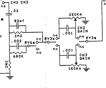 This picture shows the layout for the load and voicing circuit. The voicing is controlled by relay 6a. I believe the normally open and normally closed poles are actually reversed from the way it is shown.
When Raw is selected, relay 6 in the voicing circuit relay (not shown) closes. Relay 6a should break the parallel connection to the 680 k resistor and .002 pf capacitor, removing them from the signal path. I’ll show my reasons for believing this as we go through this post.
When Vintage or Modern are selected, all three resistor are put in parallel to each other. 2.2 M||2.2 M||680 k = 420 k is the resistance for the load and voicing. Combined with 2.082 n, 1.1 M gives a boost to frequencies above 182 Hz.
When Raw is selected, relay 6a goes to the open pole, leaving the 2.2 M||2.2 M resistors in parallel. The load and voicing resistances become 1.1 M. 82 pf is parallel with the 1.1 M voicing resistance. The treble boost cutoff is moved to 1.7 kHz.
Having the voicing for Raw that high reduces the gain of everything below that knee. Additionally, the feedback from Presence circuit for Raw attenuates and compresses frequencies down to 34 Hz. The Presence pot being post-EQ also works against the 1.7 kHz treble boost, though less so on Channel 3 with it’s higher filter.
Voltage Division
It seems counter-intuitive at first that Raw would have a higher gain than Modern and Vintage. This becomes moot when considering the voltage divider formed by the voicing resistance and the volume pot.
When Modern or Vintage are used, the maximum amount of signal allowed to pass is about 37.3% (420 k and 250 k). When Raw is selected, the maximum amount of signal allowed to pass is about 18.5% (1.1 M and 250 k).
A quick tangent: One modification being done to the Rectos involves increasing the value of the Gain pot to 1 M. This allows more signal to pass. Vintage and Modern would now allow 70% and Raw would pass 66%. Increasing the resistance also darkens the sound.
Relay 6a Revisited
The difference in signal going to stage 2 is the biggest reason I think the schematic is wrong about the n.o. and n.c. poles for 6a. That difference alone would account in the significant drop in volume when switching to Raw.
The 1.7 kHz high pass filter on the 2.2 M/82 pf filter is another consideration, since it reduces the amount bass and mids allowed to pass. On the Raw mode, the filtering later on in the amp would reduce distortion and brightness, offsetting the brightness of this filter.
Were it on Modern and Vintage, that treble boost would be incredibly harsh. While stage 3’s filter would also reduce this boost, it would be receiving significantly more treble than other frequencies, resulting in a sound much like a Big Muff with the tone control fully clockwise and no negative feedback to smooth it out.
Gain Control
Both channels use 250 k pots for the Gain control. There’s a 1 nf cap from lug 3 to the wiper of each to give a treble boost similar to the circuits above. The resistance that interacts with the cap becomes smaller as the pot is turned up and it increases the cutoff as described below.
Function of a Treble Boost Cap
When a pot is used without a treble boost cap, the lower regions of the taper will greatly reduce the high frequencies and can sound really dull, because treble has a harder time getting past the resistance. The cap alleviates that. The effect is less pronounced as the pot is turned up. This is the reason behind the information regarding sweet spots in the manual. Lower settings will appear to be brighter. Since the high frequencies are coming through, the Gain doesn’t have to be cranked to have saturated upper harmonics and will sound balanced somewhere in the middle regions on the dial.
Treble Boost
The cutoff of the treble boost increases as the pot is turned up: 9:00 is 656 Hz; Noon is 707 Hz; 1:30 is 795 Hz; and 3:00 is 1.4 kHz. From 9:00 to Noon and from Noon to 1:30, the differences are not that great. As the Gain is increased, the overall amount of signal is increasing and the cap contributes brightness until around 2:30.
At greater Gain settings, the cap makes little difference as a treble boost, because the overall signal is now large and the cut off becomes higher. This contributes to the grainy sound as the control rounds 2:00 to 3:00. As shown above, at 3:00 the cutoff is 1.4 kHz. At that point, the treble and harmonics are passing right through at a great volume.

[…] Channels 2 and 3 Part 1: Mesa Rectifier Design Concepts […]
LikeLike
[…] Channels 2 and 3 Part 1: Mesa Rectifier Design Concepts […]
LikeLike
[…] Channels 2 and 3 Par… on Channels 2 and 3 Part 1: Mesa… […]
LikeLike
I’ve been recently toying with Mark series circuit design for kicks. I’ve made some interesting observations which relates to SLO and Recto designs as well I believe.
As is well known, Mark series employs pre-gain tonestack right after the input triode which is derived straight from earlier Fender designs. Some have argued that the pre-gain tonestack is redundant for overdriven tones for two reasons. First, tonestack introduces high signal loss which essentially requires using one triode to restore the signal. Second, as the pre-gain tonestack practically bears only gain shaping function on overdriven tones, it tends to be set within particular narrow setting: bass very low, treble reasonably high, and mids somewhere above noon.
I wondered that If the tone is only set to one particular setting and kept there, why would I need the tonestack at all? Removing the tonestack would allow removing the recovery stage as well which would simplify the circuit while still having enough gain to drive the lead stages in Mark type lead circuit.
I played with LTSpice to compare frequency responses and signal levels between my preferred settings with different circuit alternatives to match the curve. I found that the most simple way to create very similar curve was 22nF coupling cap in series with 1Mohm/1nF RC-circuit, followed by 1Meg gain pot. Does this ring bells at all? It is identical to Soldano Avenger treble peaking circuit. If you play with the values, you can turn the values to 470k/2.2nF with 500k Gain pot which is straight from Soldano SLO. Rectifier series effectively has the same circuit with the 2M2 resistor to ground and 250k gain pot.
This reminded me about discussion of Soldano SLO being influenced by Mesa Mark. While the circuits are very different, I think the first stage in SLO essentially represents one fixed setting from Mark tonestack. While circuitwise, SLO has much, much more common with Marshall 2203/2204, making it rather a hot-rodded Marshall, the first stage of SLO could be tonally influenced by the Mark series in this aspect – or, possibly teaching Soldano there’s no use for pre-gain tonestack in high gainers.
LikeLike
Hi. Long time, no see.
I’ve come to believe the information about Soldano being influenced by the Mark series was a troll at work. The SLO is a modded Marshall design.
In reference to the tone stack between stages 1 and 2, the second stage is indeed for makeup gain. Removing the tone stack would require stage 2 to be altered.
I think you are correct with the assumption that what actually was the classic Marshall design was a evolution of the Fender design. I believe it occurred after the Blues Breaker. Moving the tone stack and changing stage 2 led them to use the coupled cathode follower to maintain as much gain as possible going into the tone stack at the end.
Initially, it was two separate inputs using V1’s stages separately. Then they were altered by guitarists during the Plexi years by either jumping the inputs or what’s called the “One Wire Mod”, so as to use both sides in series-parallel. This was further modified by Marshall to become the modern JCM series when stage 1 was fed to stage 2 and stage 3 had the cold clipping introduced. That increased the gain high enough that when the ccf fed into the tone stack the loss was mitigated.
Really, some loss of gain is not a bad idea. The rc circuits after each stage limits the gain between them to a manageable amount and a narrow frequency range, so the valves aren’t overloaded or unstable.
I think Soldano recognized the need for attenuation in his design. The second stage loses about half going into 3; stage 3 has less than a gain of 2; and the parallel resistance out of stage 3 reduces the accumulated gain by more than half. Mesa played around with that preamp to achieve their desired tones. There is still loss at the input of the tone stack, as mentioned above.
The point is: which design is used is a question of the desired tone. Yes, the loss up front is great and requires whatever number of additional gain stages to get the desired drive, but each design has a particular tone. The tone stack will also react differently in each location.
Moving the tone stack to the end may need a buffer. The ccf does that, but also clips one side of the signal nearly right off at high gain settings and has a distinct effect. The cold clipping with the large resistance, ala Soldano or Mesa, helps shred the entire signal with varying degrees of clipping on each side, in concert with the ccf.
In any case, if either design is chosen for a high gain amp, it will need about the same amount of triodes to achieve comparable clipping and volume. Even the later EVH/5150 amps use no ccf or cold clipping, but uses several stages after stage 2 to increase the gain. As a comparison, Diezel uses more stages on top of that for the VH4’s highest gain stage. (I believe, haven’t got it in front of me.)
I’m still ill. My mind kind of aches now. I hope that made sense and was completely relevant to what you seek.
Thanks.
LikeLike
Thanks for sharing your thoughts.
Yeah, I agree with you. SLO and Mark series circuits bare practically zero resemblance. If you simply add one gain more stage in front of 2203/2204 Marshall with MV, you essentially have a circuit structure identical to SLO. I think it is the most commonly adapted design. Amp builders such as Bogner, Fortin, Friedman also use that same formula, but with even lesser changes to the basic 2203/2204 part. In this aspect, it is refreshing to see some more original designs as Diezels you mentioned, or ENGLs, which have their own thing going on.
Back to the Mesa Rectifier design, I think the 250k gain pot is actually a really good design choice in this circuit. It seems to allow the 2.2nF/470k circuit to function more effectively. I also think SLO has too much gain up front and 250k pot is much more balanced. I’ve also tested the circuit without the load 2M2 resistor. The low-end became somewhat spongy from that and I quickly put the resistor back.
LikeLike
Not to insult your intelligence, I can explain the difference between a 1M pot and a 250k pot.
The voicing circuit in the Rectifiers is the upper resistance in a voltage divider against the lower resistance of the 250k pot. We can look at maximum results with the pot rotated all the way up.
In Vintage or Modern, the total voicing circuit resistance is 519k. When the pot is 250k, only a maximum of 32% of the signal passes. Under the same conditions, but using a 1M pot, about 52% of signal passes. In both cases, the capacitor on the pot is shorted and doesn’t make anything frequency dependent.
On a SLO, the 470k grid resistor and a 1M pot would let a maximum of 68% pass. A 250k pot would reduce it to 34%. That’s closer to a Rectifier.
The lesson, as you noted, is about controlling the signal. Mesa decided a 250k pot produced enough signal for their needs. Indeed it is and works well, even though it seems like a massive loss on paper.
Side note: Design choices like the voicing circuit and gain pot value are among their contributions to the basic Marshall/SLO design. It’s one example of why the Rectifiers sound different and why they aren’t just SLO ripoffs.
The Diezel VH4 design kind of takes the initial stages of a Marshall design and marry it to a Mark IV’s cascading design. Maybe not literally, but he eschewed cold clipping by using multiple cascading stages for a massive, firm crunch.
LikeLike
@Warpedpig#1 Question about gain pot values. Can you explain from the technical / electrical point of view why exactly using 250k leads to “loose tone”, “muddy low end”, and “too much bass”, while 1M leads to “tight and balanced tone” and “gives you more wide control of gain”? How do these 32% and 52% (taken from your post) contribute to the quotes above?
Quotes are taken from here: https://www.thegearpage.net/board/index.php?threads/someone-built-the-mesa-boogie-dr-clone-from-the-ampclones.2028650/#post-28834503
LikeLike
A lower value might not lead to muddy tone or loose tone. It’s basically like this: lower numbers are darker and higher numbers are brighter. It’s because resistance is one half of an RC or LR filter. The lower the number, the lower the cutoff.
What’s so far not taken into consideration here is the source’s content. Is it really bright? Drop the pot value. Is it really dark? Increase the pot value. A dark signal, which would sound flabby on a Recto, would be more balanced with added mids and treble. In the same way that cutting the bass frequencies back will bring the mids out more prominently, increasing the top would sound like the bass is diminishing, even if it’s not. This gets into psychoacoustics, which is beyond what I can teach.
Pickups are an example of the above. Single coils tend to be really bright. The normally use a 250k pot. EMGs use a 25k pot, they are extremely clear and bright Conversely, humbuckers tend to be darker. The normal value of the pot is 500k.
I don’t think the amount of signal passing necessarily affects the treble content.
LikeLike